Designing Cervical Inlay
In Medit ClinicCAD, users can create inlays for treating cervical abrasions; we refer to them as 'cervical inlays.'
Tip
There are several reasons why inlays may be more advantageous than resin fillings:
more secure bond in areas of extensive cervical loss
less discoloration over time
more durable than traditional fillings
eases and shortens the treatment process
The final design of a cervical inlay includes three components: an inlay, a setting guide, and a setting guide grip.
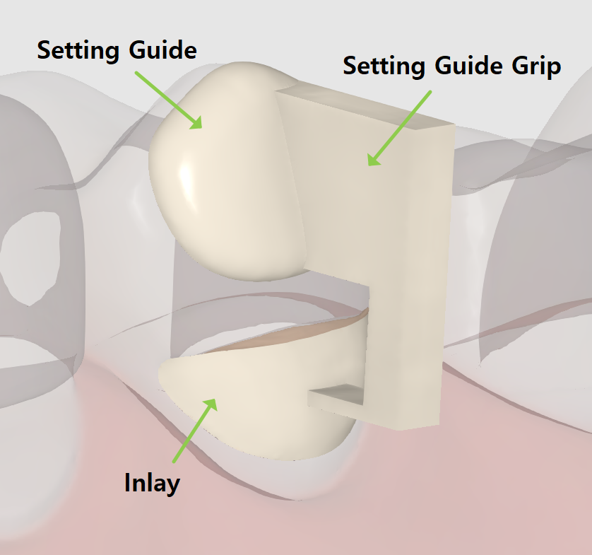
The setting guide and the grip are designed to assist restoration placement and can be easily removed afterward. The setting guide is an obligatory element that is created automatically about 1 or 2 mm from the abrasion area. If needed, users can modify it by editing its margin. The setting guide grip is optional and can be added at the final step.
The cervical inlay workflow includes only 2 steps: Margin & Insertion Path → Final Design.
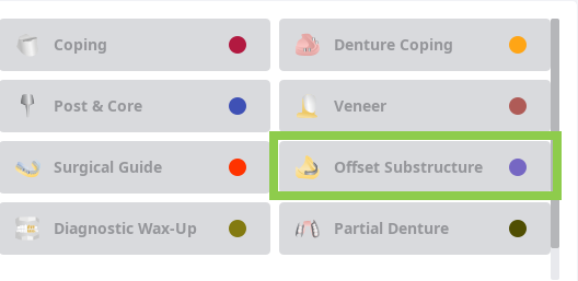
To begin, register your inlay as "Offset Substructure" in the Medit Link form. Then, run the app and select the Prepared Data module.
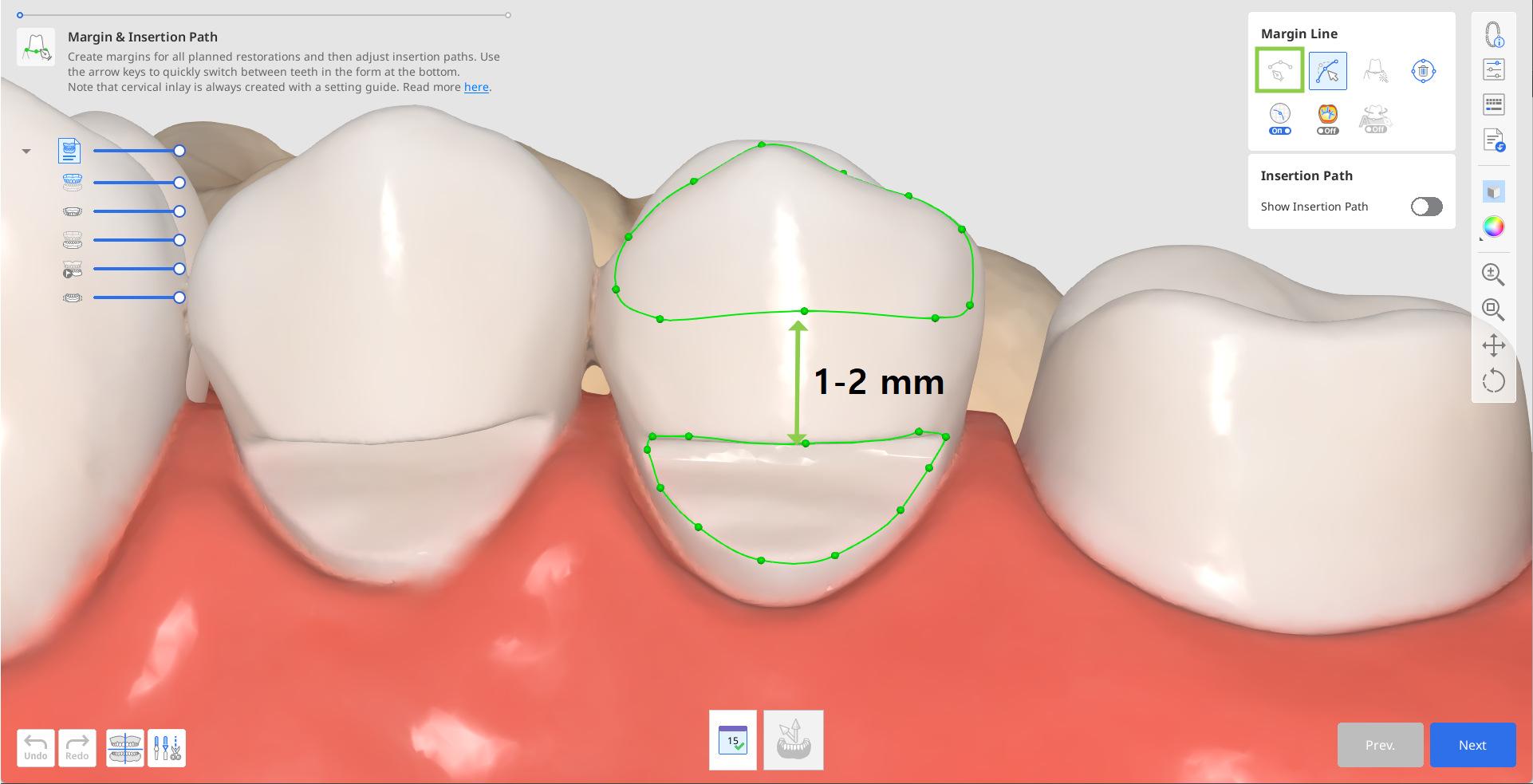
In the first step, draw a margin for the inlay using the “Auto Creation” or “Manual Creation” tool.
”Auto Creation” draws a margin based on one clicked point; “Manual Creation” draws a margin based on multiple points.
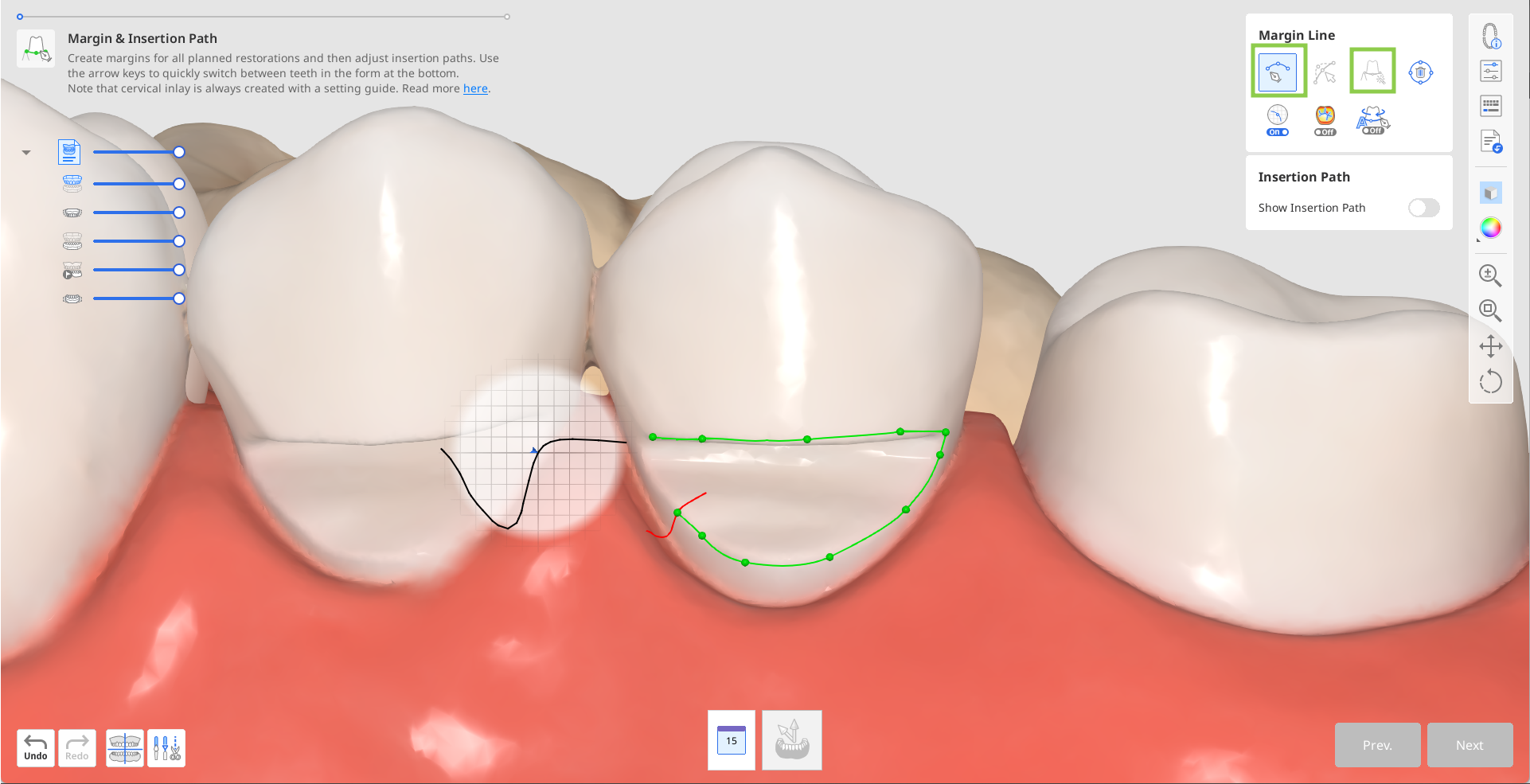
The setting guide margin will be created automatically.
If automatic creation fails, manually draw the setting guide margin, leaving about 1 or 2 mm between the two.
 Caution
The mm values in this document are recommended design parameters, not measurement outputs from the software.
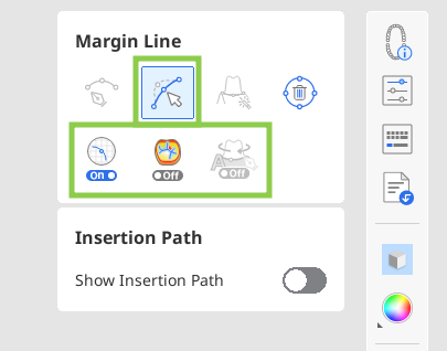
If needed, edit the created margins with the “Edit” tool. Utilize the other provided margin line tools to assist you in creating a more precise margin.
 Tip
TipWhen editing, hold down the Ctrl/Command key and drag the mouse to make minor freehand corrections quickly.
After the margins are created, the insertion path arrow will appear. Adjust it to face toward you by dragging it with a mouse and click "Next."
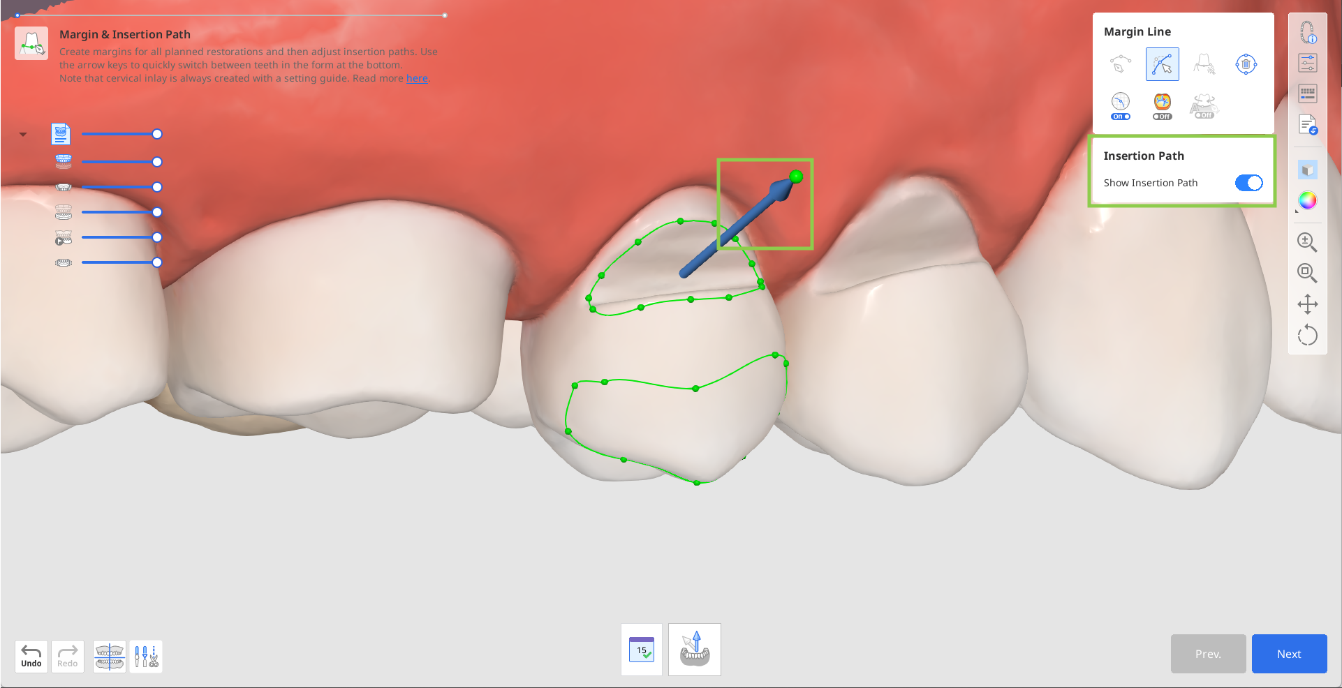
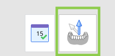
Alternatively, you can rotate the 3D data and click “Set Arrow to Your Viewpoint” at the bottom.
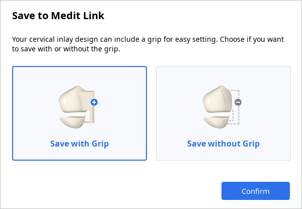
In the next step, you can add the grip that will assist holding the inlay design when setting. For this, turn on "Setting Guide Grip" on the right.
Or you can substitute the grip for supports later in your printer software.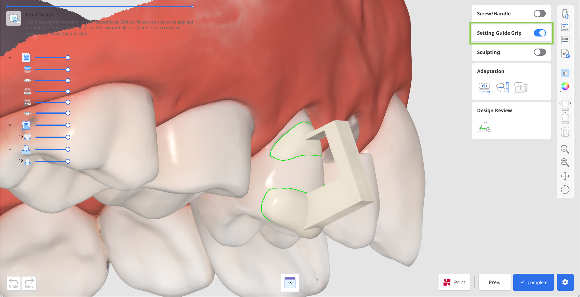
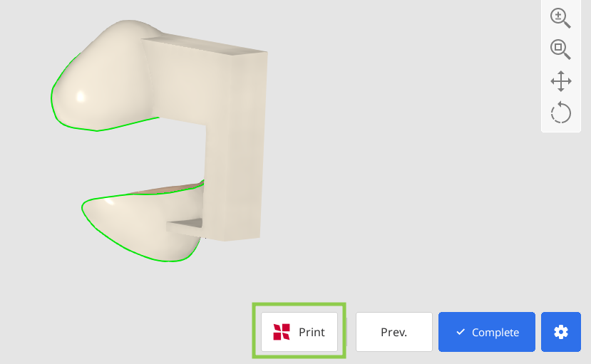
Click "Complete" to pay for the export of your design and save it to Medit Link. The app will double-check with you on creation of the grip.
If you have a SprintRay 3D printer, you can transfer your restoration design from this step right into the RayWare Cloud. For this, use the “Print with SprintRay” at the bottom and follow the guidance on the screen. You must already have a RayWare Cloud account to use this feature and pay for the design before proceeding with printing.
 Caution
If you encounter difficulties connecting to RayWare Cloud, please refer to the following troubleshooting guidelines:
check your internet connection
verify your login credentials (username and password)
review your restoration design
If the issues persist, please reach out to SprintRay support.
Recommended 3D Printer Specifications
This software and workflow have been validated based on a 3D printer with the following performance specifications:
Printer Type: 405 nm DLP 3D printer
XY Resolution: approximately 95 μm or less
Layer Thickness: adjustable within the range of 50–170 μm
Dimensional Accuracy: approximately 130 μm (reference value: 129 ± 16 μm)
Supported File Formats: STL, OBJ, SPR
Any 3D printer with performance specifications equal to or higher than the above can perform similarly to Pro95S, a manufacturer-validated device.
If using a different 3D printer, verify that the device meets the above requirements. If necessary, contact the manufacturer or perform your own print quality evaluation.
List of Validated CAM Equipment
The list of validated CAM equipment and the corresponding parameter settings may be updated based on manufacturer verification results. Please check our website or contact customer support for the latest information.
Company Name | Product Name | Printer Type | Material Type* | Parameter Settings |
|---|---|---|---|---|
SprintRay Inc. | Pro 95S | 405 nm DLP 3D printer | Ceramic Crown | Min. thickness 0.5 mm; cement thickness 0.11 mm; cement starts at 0.8 mm; margin width 0.1 mm |
*This workflow has been validated based on dental-use resins designated by the manufacturer and the materials used according to the resin manufacturer’s Instructions for Use (IFU). If using other materials, the user must independently evaluate whether they meet the performance requirements above and are clinically appropriate.