Main Toolbar Tools
- 02 May 2024
- 12 Minutes to read
- Print
- DarkLight
- PDF
Main Toolbar Tools
- Updated on 02 May 2024
- 12 Minutes to read
- Print
- DarkLight
- PDF
Article summary
Did you find this summary helpful?
Thank you for your feedback
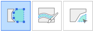
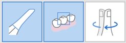
Trimming Tools
Trimming tools help to edit and remove noise from the data.
| Polyline Trimming | Remove all entities within a polyline shape drawn on the screen. |
| Brush Trimming | Remove all entities on a freehand-drawn path on the screen. Only the front face will be selected. The brush comes in three different sizes. |
| Quick Trimming | Remove data detached from the rest of the data quickly. |


Polyline Trimming
- Click the "Polyline Trimming" from the Trimming tool on the main toolbar.
- Draw a polyline around the area you want to delete in the 3D data.
- Delete the selected region by right-clicking on the mouse.


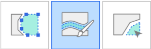
Brush Trimming
With Brush Trimming, you can remove all entities on a freehand-drawn path on the screen. The following tools are provided at the bottom of the screen when you select the Brush Trimming tool.
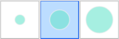
| Brush Size | Set a brush size. The brush comes in three different sizes. |
| Manual Noise Trimming | Remove unnecessary noise data in the area selected with a brush. |
| Auto Noise Trimming | Remove unnecessary noise data automatically according to the viewing direction. |


- Click the "Brush Trimming" from the Trimming tool on the main toolbar.
- Select the brush size at the bottom.
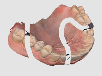
- Select the areas where noise should be trimmed. Only the front face will be selected.
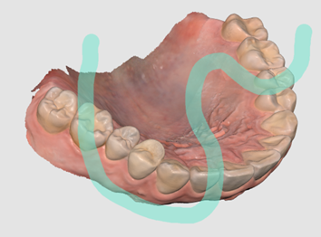
- The selected area is automatically deleted after selecting the area with the mouse.


Manual Noise Trimming
You can manually remove the unnecessary noise data.
🔎Note
When this option is off, you can select an area with a brush, but the area is not removed.
- Click the "Manual Noise Trimming" tool icon at the bottom.

- Select the brush size at the bottom.
- Select the areas where noise should be trimmed.
- The selected area is automatically deleted after selecting the area with the mouse.
Automatic Noise Trimming
You can automatically trim unnecessary soft tissues such as lips, cheeks, and tongue.
- Click the "Automatic Noise Trimming" tool icon at the bottom.

- The program automatically removes unnecessary soft tissues.
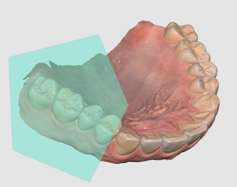
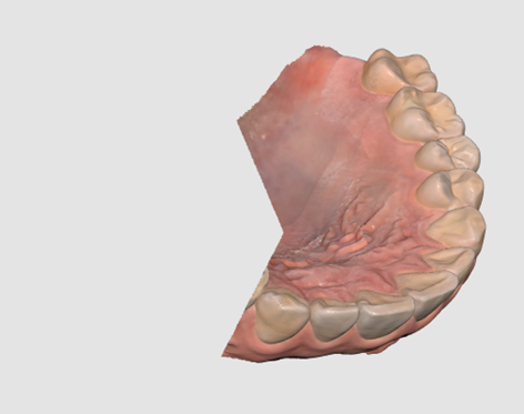
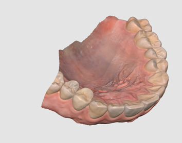
Quick Trimming
- Click the "Quick Trimming" from the Trimming tool on the main toolbar.
- Click on data separated from the rest of the scan data.
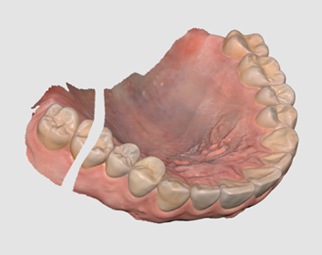
- The isolated area where you clicked is removed as below.


Function Tools
| Lock Area | Lock a specific area using the selection tools. |
| Undercut Analysis | Analyze the undercut area based on the direction of insertion. |
| Swap Maxilla and Mandible | Swaps maxilla and mandible scans. This is useful if the operator accidentally scans the wrong jaw. |
| Result Preview | Show the preview of the selected area to check the quality of data before actual processing. |
| Margin Line | Creates a margin line automatically or manually. The margin line information can also be imported into a design program. |
| Smart Data Cleaning | Filter out soft tissue data by removing unreliable data using the Reliability Map. |
| Scan Replay | Replay the scanning process. |
| HD Camera | Take 2D images with 3D model data and share the images with a laboratory. |
| Register Abutments | Register an abutment in the library by scanning it yourself or importing it. Once registered, you can use it for Abutment Library Matching. |
| Smart Shade Guide | Provide smart shade recommendations. |


If you select one of the above function tools on the Main Toolbar, the following selection tools are shown at the bottom to work on the function.
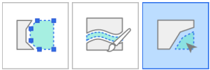
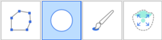
| Polyline Selection | Select all entities within a polyline shape drawn on the screen. |
| Circle Selection | Select all entities within a circular area. |
| Brush Selection | Select all entities on a freehand-drawn path on the screen. The brush comes in three different sizes. |
| Smart Single Tooth Selection | Automatically select the area of a single tooth with a click. You can click or drag on the tooth. |
| Selection | Enable the selection mode to select areas using the selection tools above. |
| Deselection | Enable the deselection mode to unselect areas using the selection tools above. |
| Clear All Selection | Clear the entire selection. |
| Confirm | Apply the results for the selected tool. |


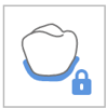
Lock Area
You can lock a specific area using the selection tools so that further scanning cannot affect the shapes of the locked area but the color.
🔎Note
This feature is useful when preserving the retracted gingiva data scanned after cord removal.
- Click "Lock Area" from the Main Toolbar.

- Select an area to lock with area selection tools.
- Select the area you want to lock. The selected area is presented in a different color.


You can unlock the locked area by doing one of the following:
- Click the "Deselection" tool icon to switch to the deselection mode, select a selection tool, and mask the areas to unlock.

- Click the "Clear All Selection" tool icon to unlock all locked areas.


Undercut Analysis
Analyze the undercut area based on the direction of insertion. The insertion direction can be determined by Auto Direction or Manual Direction.
| Auto Direction | The system automatically calculates the direction in which the undercut area is minimized. Then, it displays the undercut area on the View Screen. |
| Manual Direction | The system calculates the undercut area based on the view direction of the user. The user can change the view direction by moving or rotating the data. Then, it displays the undercut area on the View Screen. |


Undercut Analysis with Auto Direction
- Click the "Undercut Analysis" tool icon from the Main Toolbar.

- Select the region of interest to calculate the undercut area with area selection tools.
- If no area is selected, the program will calculate the undercut area for the entire 3D model in the data display area.
- Click the "Auto Direction" icon at the bottom.

- An insertion path arrow appears in the direction where the undercut area is minimized, and the undercut areas are presented in dark blue.
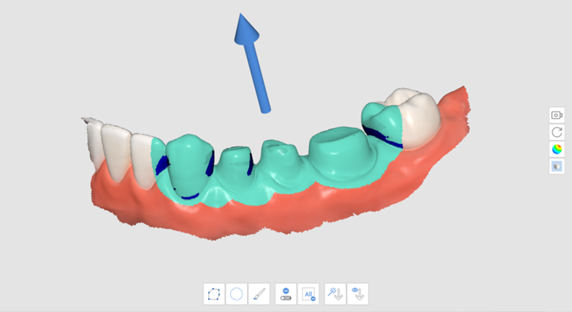
- You can change the direction of the insertion path by left-clicking and dragging the arrow.


Undercut Analysis with Manual Direction
- Click the "Undercut Analysis" tool icon from the Main Toolbar.
- Select the region of interest to calculate the undercut area with area selection tools.
- Use the "Move," "Rotate," "Zoom In," and "Zoom Out" tools on the Side Toolbar to change the model's direction.
- Click the "Manual Direction" icon at the bottom.

- An insertion path arrow appears in the direction of the user's viewpoint.
- You can change the direction of the insertion path by left-clicking and dragging the arrow.
Swap Maxilla and Mandible
When the mandible is scanned in the maxilla scan stage by mistake or vice versa, you can correct it using this feature.
- Click the "Swap Maxilla and Mandible" tool icon from the Main Toolbar.

- The current data at the Maxilla and Mandible stages are swapped.
Result Preview
- Click the "Result Preview" tool icon from the Main Toolbar.

- Select an area to preview with area selection tools.
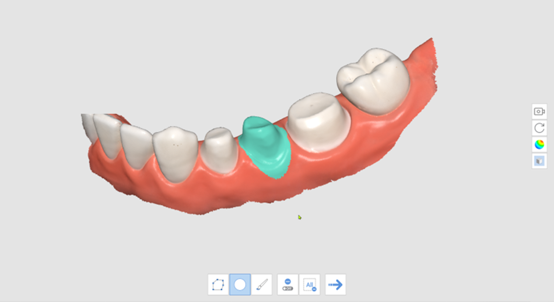
- Click "Next Step" to view the result.

- Preview the result.
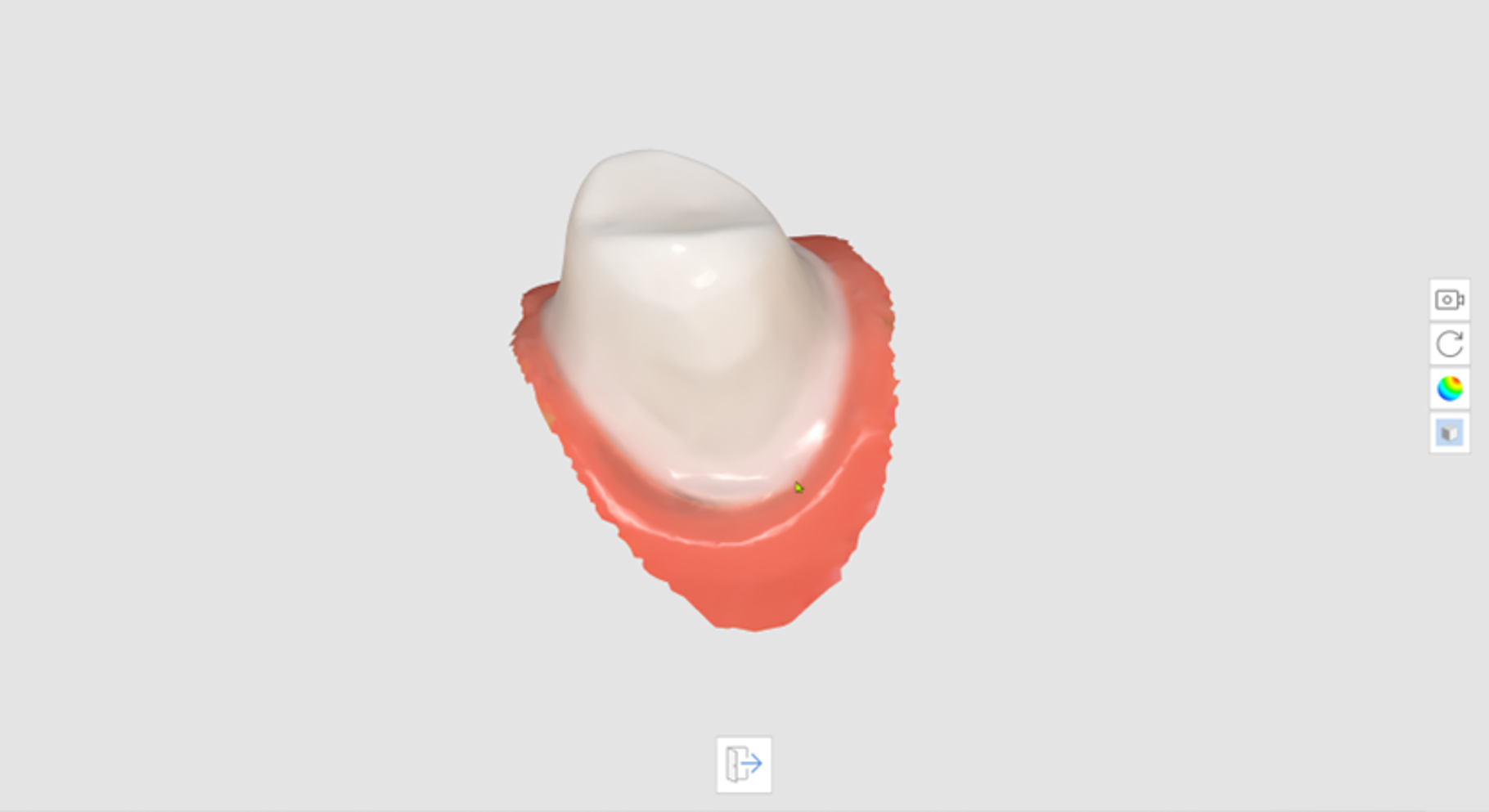
- Click "Exit" to go back to the previous step.


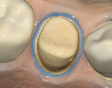
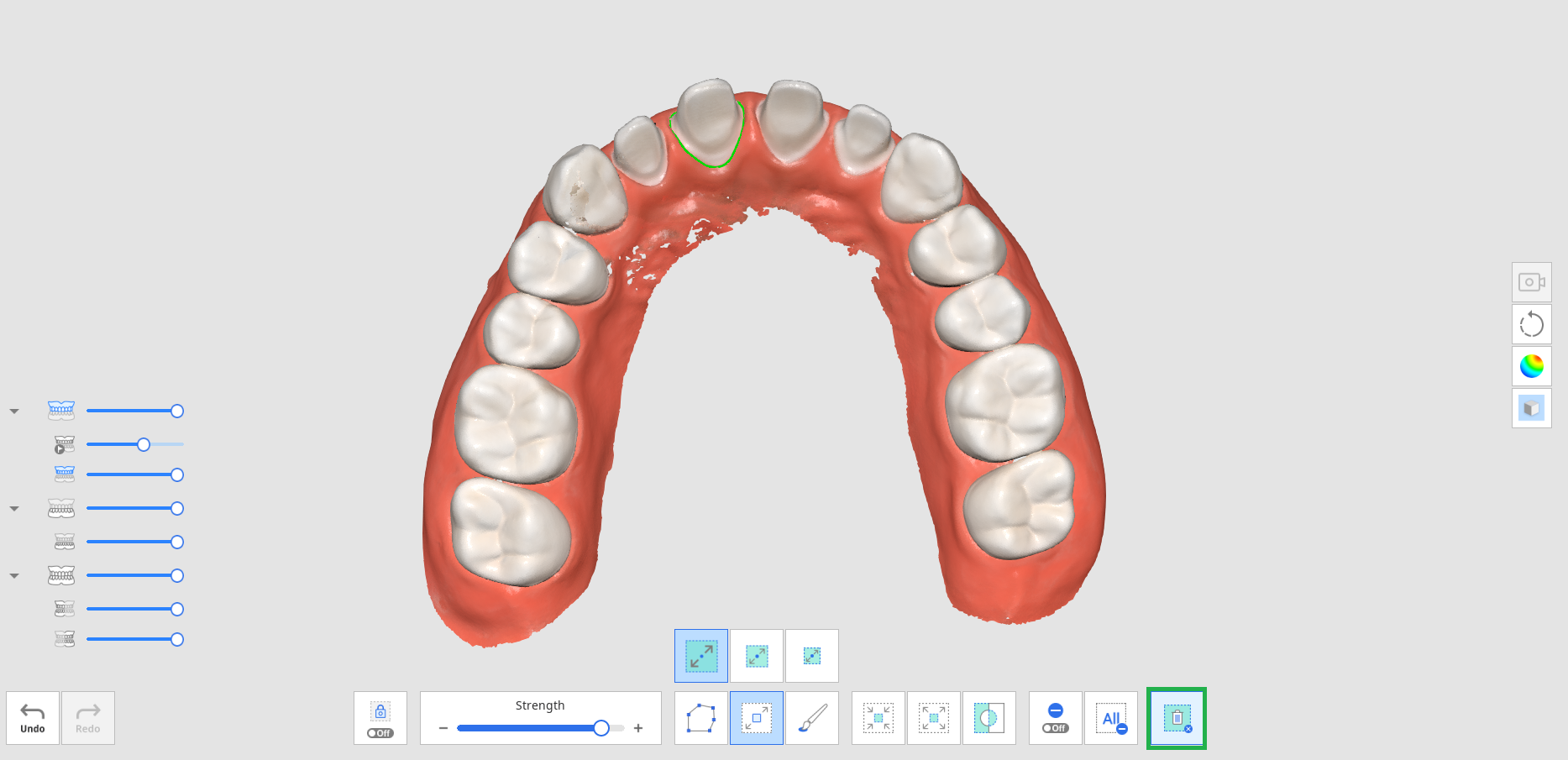
Margin Line
The following tools are provided for the Margin Line feature.
| Auto Creation | Create a margin line automatically based on the points selected by the user. By selecting multiple points, a closed margin line will be created. | ||
 | Dynamic View Change | Turn this option on to automatically rotate data according to the view direction. | ||
| Manual Creation | Create a margin line manually according to the points selected by the user. | ||
| Edit | Enable editing the margin line. The user can add, move, and remove the control points of a margin line. | ||
| Delete | Delete the margin line. | ||
| Curvature Display Mode | Measure the surface curvature of data to display the data in different colors through a color map.
If the color is redder, it is more embossed, and if the color is bluer, it is more engraved. You can use the color expression interval slider to adjust the color radius. | ||
| Section View | Show the cross-section of the area where the mouse pointer is located.
It prevents any areas from being hidden when zoomed in closely and allows you to check the magnified margin more carefully. |


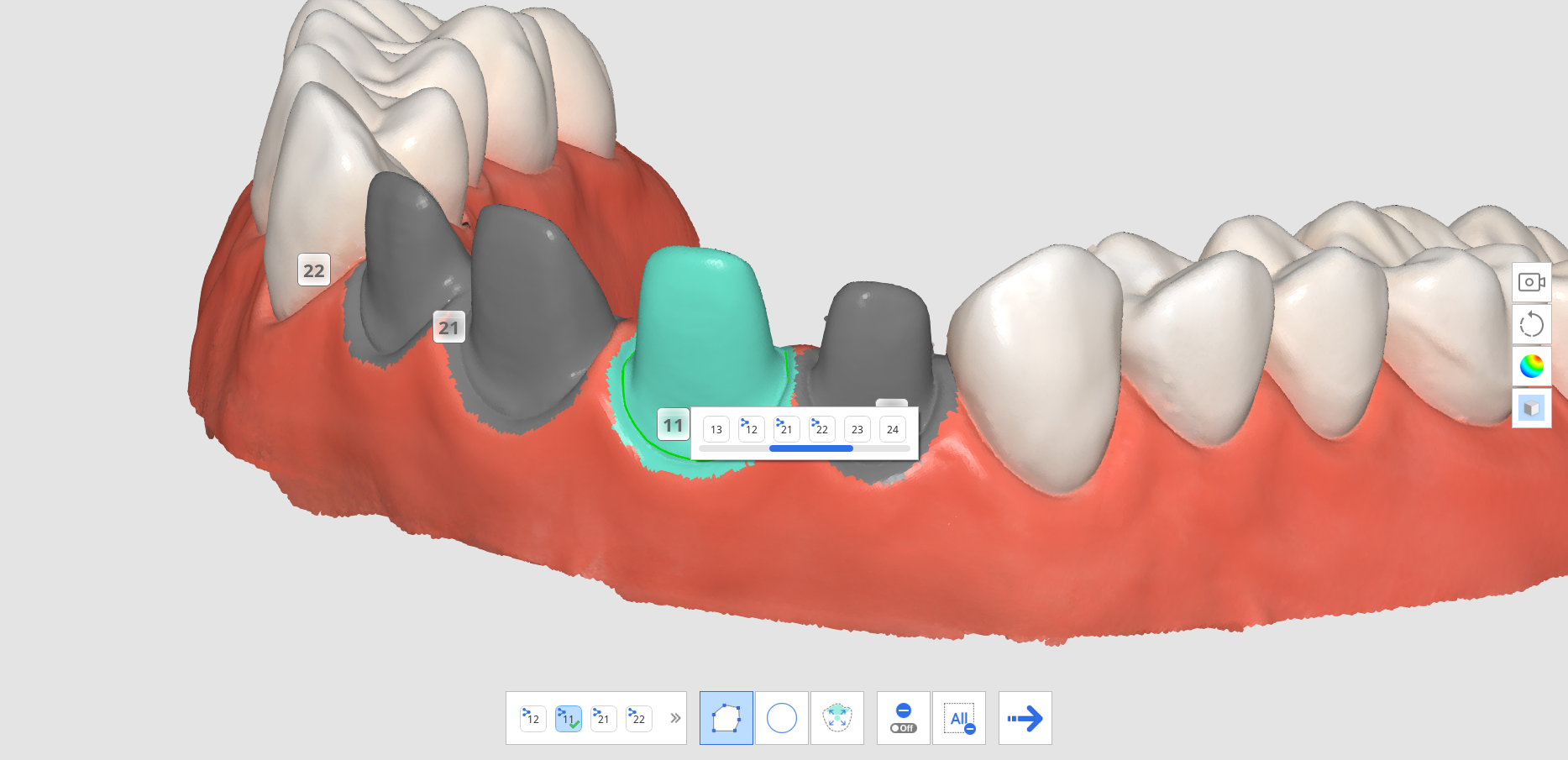
- Click the "Margin Line" tool icon from the Main Toolbar.

- Select the Maxilla or Mandible stage.
- Select a tooth number.
- Select an area for the selected tooth number with area selection tools, and click the "Next Step" icon.
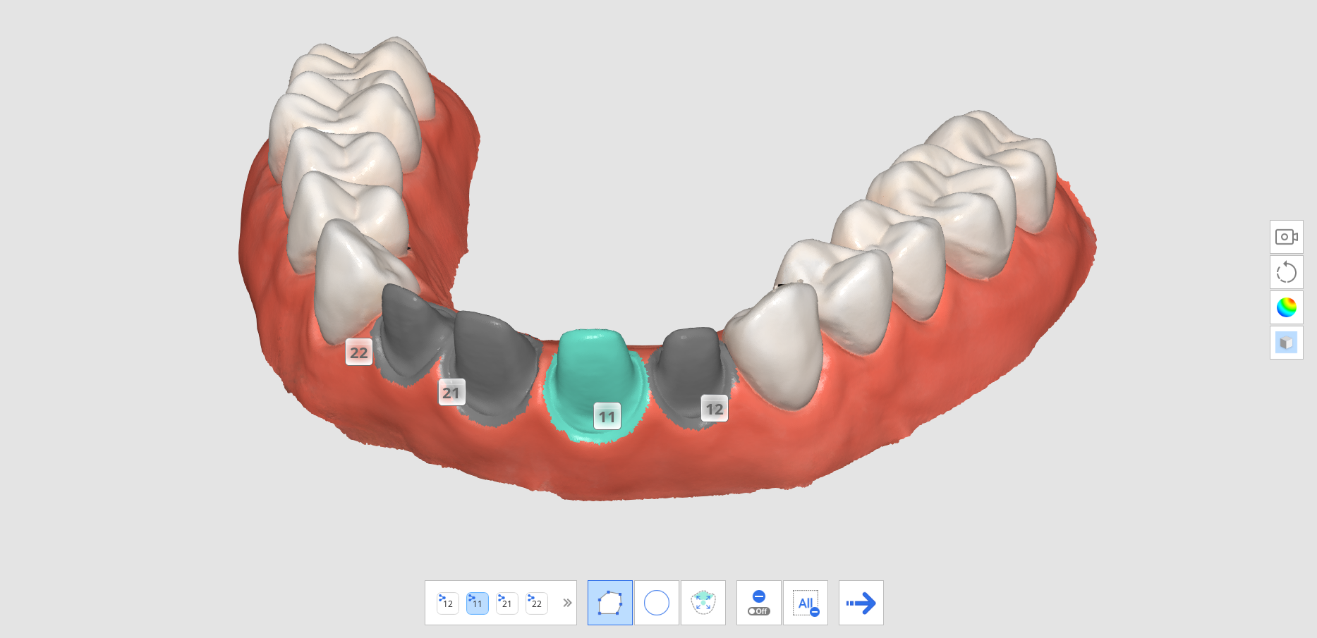
- Click the "Next Step" icon.
- The system generates a temporary result with the selected area. You can create a margin line using this result data.
- Click the "Auto Creation" or "Manual Creation" icon to draw the margin line.
- Auto Creation: Click the "Auto Creation" icon and select points. Then, the margin line will be automatically created based on your selected control points.
- Manual Creation: Click the "Manual Creation" icon and mark points along the margin line using the left mouse button to link each point to the next. Hold and move the mouse to fine-tune the position of the point on the Section View.
- You can make adjustments by clicking the "Edit" icon.
- Add a control point: left-click on the margin line
- Remove a control point: right-click on a control point
- Move a control point on the 3D model: left-click on a control point and drag
- Move a control point on the section: left-click and hold for 1 sec on a control point and then drag
- Click "Exit" to show the margin line with the tooth number.
- You can change the tooth number for a margin line by clicking a tooth number on the 3D model view and selecting a target number from the pop-up window.
- Repeat steps 3-9 to draw margin lines for other teeth.


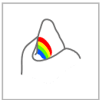
Smart Data Cleaning
The following tools are provided for the Smart Data Cleaning feature.
| Make Area Edit-Proof | Enable the user to select the area they want to protect from editing.
|
| Select Teeth Area | Select only the teeth area in the scan data. |
| Strength | Select the data with a slider bar. You can easily select and remove the soft tissue using the reliability map.
|
| Flood Fill Selection | Select all data in the connected area. |
| Shrink Selected Area | Reduce the selected area each time the user presses the button. |
| Expand Selected Area | Expand the selected area each time the user presses the button. |
| Invert Selected Area | Invert the selection of area. The selected area will be deselected, and the previously not selected area will get selected. |
| Delete Selected Area | Delete the data in the selected area. |


- Click the "Smart Data Cleaning" tool icon from the Main Toolbar.

- Adjust the "Strength" slider bar to select the amount of unreliable data to delete. The system selects data based on the reliability map and shows it in real time as you adjust the slider bar.
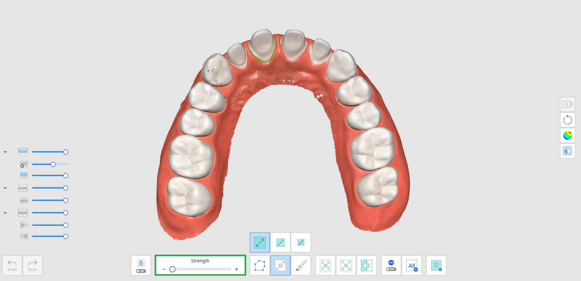
- Increasing the strength will expand selected areas.
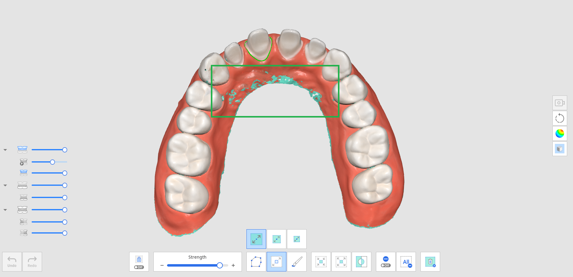
- Select areas you want to delete with various selection tools.
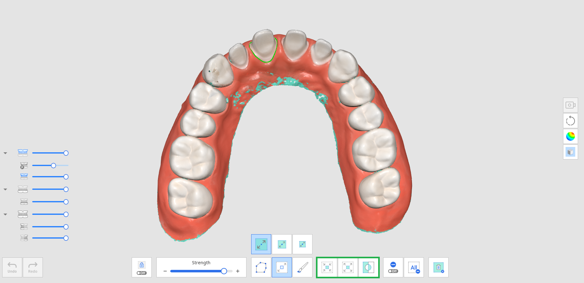
- Click the "Delete Selected Area" icon to delete all selected areas.


Scan Replay
You can replay your scanning process after scanning data in Medit Scan for Clinics. This feature is helpful for checking the scanning environment and habits of the user.
The following tools are provided for the Scan Replay feature.
| Scanner Tip | Show or hide the scanner tip during replay. |
| Scan Area | Show or hide the scanning area during replay. |
| Reverse Tip Direction | Change the direction of the tip during replay. * Unavailable with i500, i900 |


- Click the "Scan Replay" tool icon from the Main Toolbar.

- Select the scan replay options in the lower left corner of the screen. The scanner tip and scanning area will be shown in the video, depending on your selection.
- Click the "Play" button to start the replay.
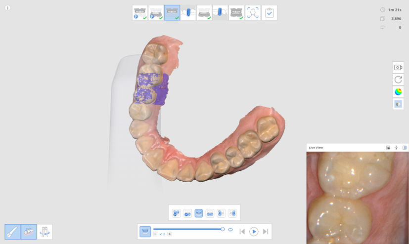
- The selected stages will be replayed in sequence.
- You can use various tools provided to control the video.


| Slider Bar | Start the video from the point of interest. |
| Video Speed | Change the speed (x0.5, x1.0, or x3.0). |
| Repeat | Play on repeat. |
| Previous Replay | Replay the scan of the previous stage. |
| Play | Start playing the scan replay. |
| Stop | Stop the scan replay. |
| Next Replay | Replay the scan of the next stage. |


HD Camera
- The HD camera feature takes high-quality images using the scanner.
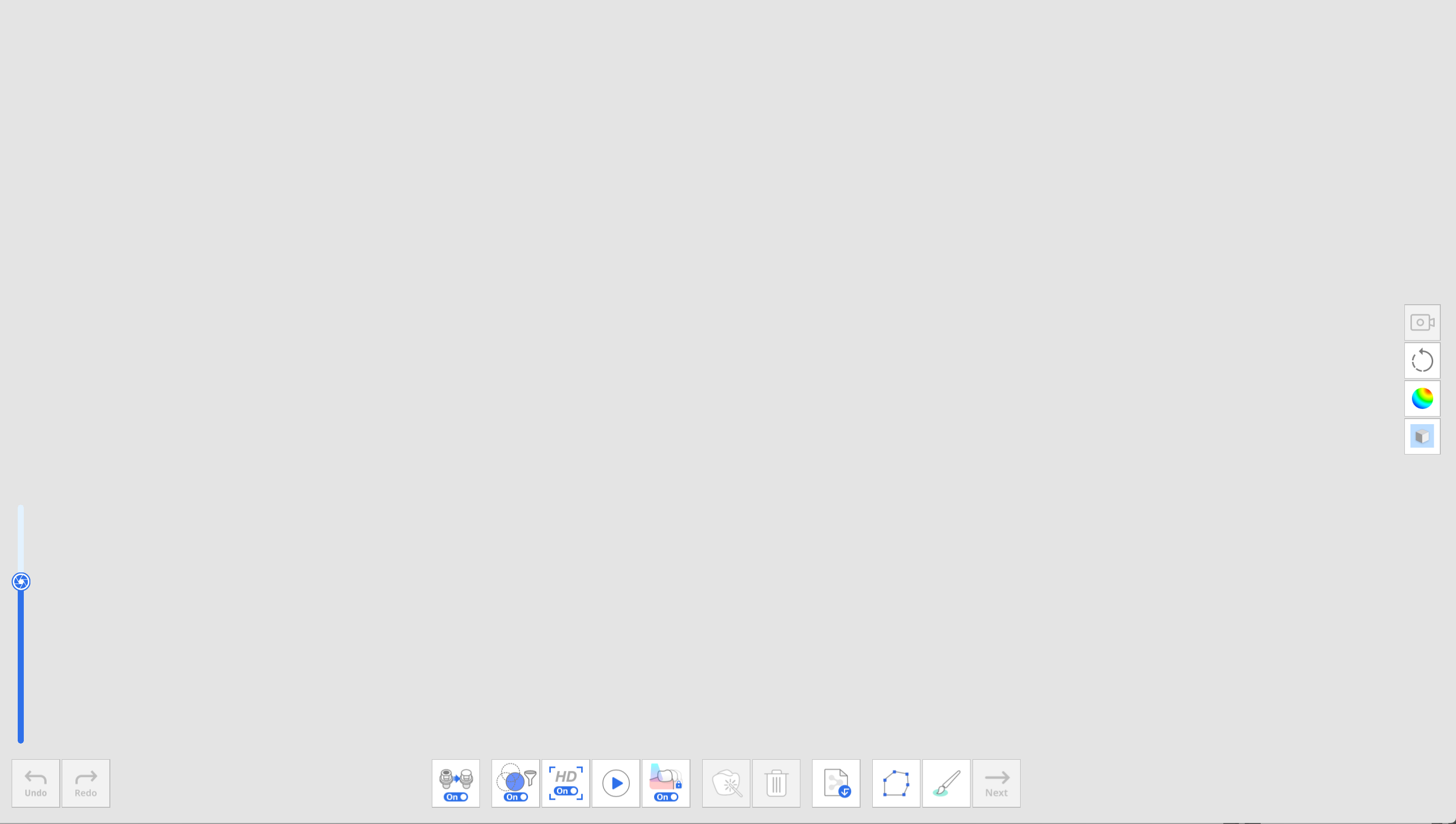
- Select the "HD Camera" tool icon from the Main Toolbar.
- The HD Camera dialog appears.
- Place the scanner tip on the region of interest.
- Press the Scan button on the handpiece to take a picture.
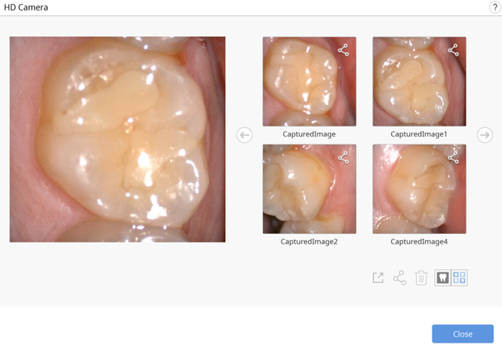
- You can rename an image by clicking on the image and entering the new name.
- You can share, export, or delete the image using the following tools provided at the bottom of the dialog.

Export the selected files to the local computer.

Share the selected image or stop sharing the image.

Delete the selected image.
Change the view style of a thumbnail.
- The captured images are saved to Medit Link as attachments when you exit Medit Scan for Clinics after saving the changes.


Register Abutments
You had to receive custom abutment files created by table top scanners in labs or even make unnecessary cases to scan the abutment and create 3D data, making it difficult to get proper use out of "Abutment Library Matching."
The Register Abutments feature allows you to scan the patient's abutment directly in their case and register it as a library. Before the implanted fixture is placed in the patient's mouth, scan the abutment first and register it as a library. Then, you can use "Abutment Library Matching" to replace the scan data with the library data.
🔎Note
Please refer to Case and Workflow Examples > Abutment Library Matching on how to use the registered abutments.
The following tools are provided for the Register Abutments feature.
| Add | Add abutments. |
| Fill Holes for Abutments On/Off | Turn the toggle on and off to fill holes for abutments while merging. |
| Merge Abutments | Merge scanned or imported abutments. |
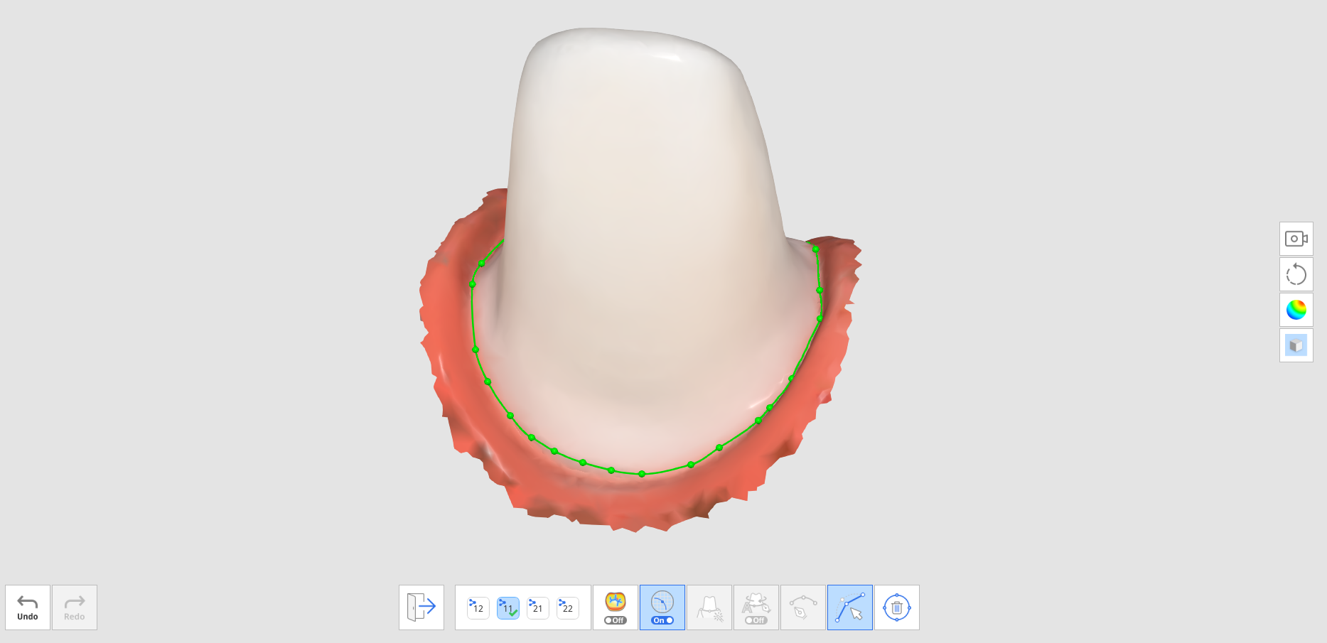
| Fill Hole From Your Viewpoint | Fill the abutment's hole from the direction you are looking at. |
| Reset Abutment | Reset to undo any changes made to the abutment. |
| Register in Library | Register the merged abutment in the library. It will be used only for that specific case if you check the box. |


- Click the "Register Abutment" tool icon on the Main Toolbar.

- You will see the above-described tools at the bottom of the screen.
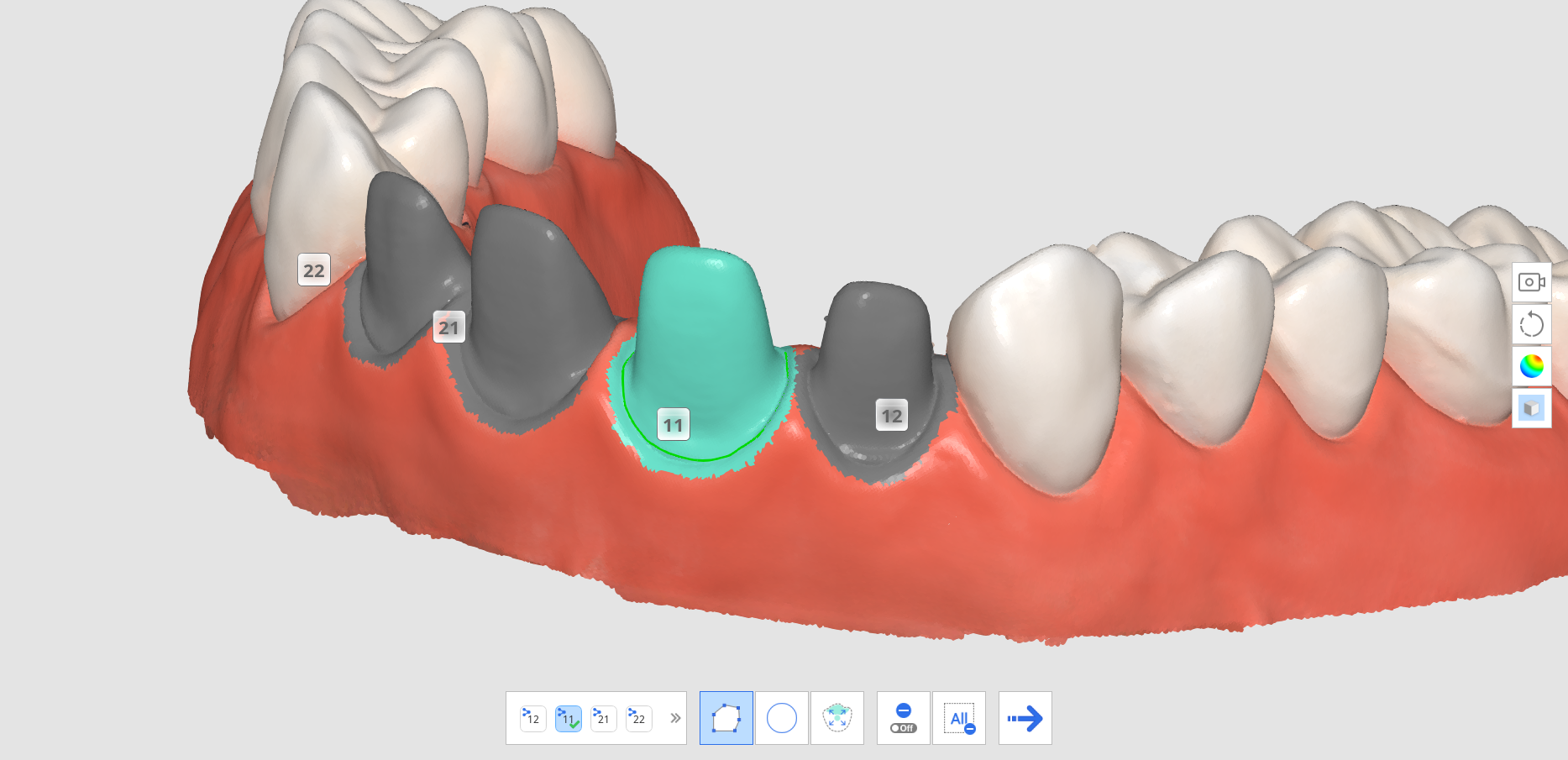
- Scan the abutment.
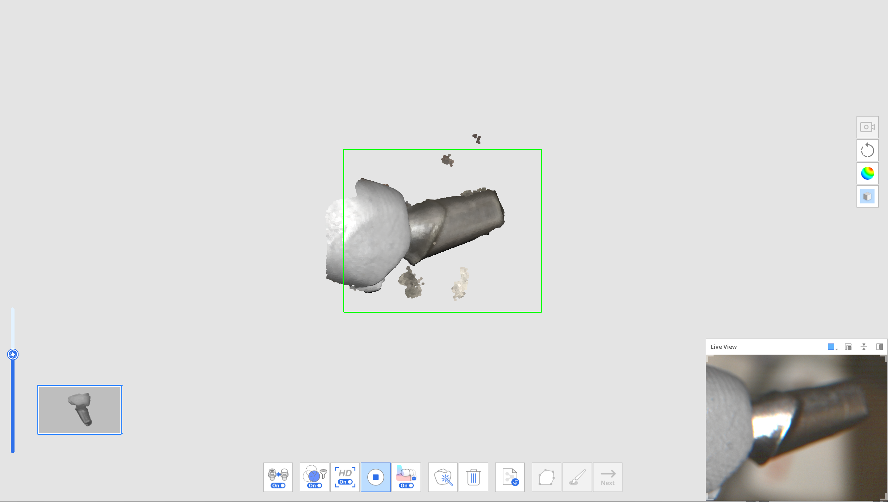
- You can edit the data using the Polyline and Brush Trimming tools when you stop scanning.
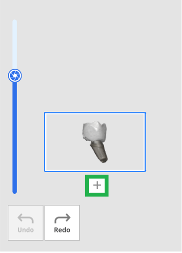
- Click the "+" button below the abutment thumbnail to scan another abutment. You can scan and register up to 6 abutments.
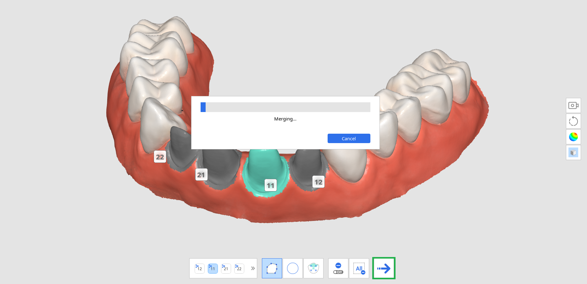
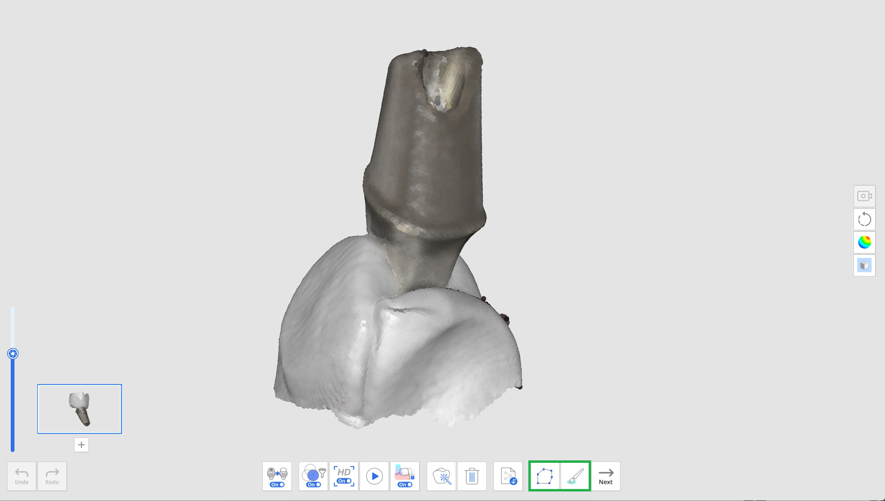
- After scanning all the abutments, click the "Merge Abutment" button to merge the abutment data for library registration.
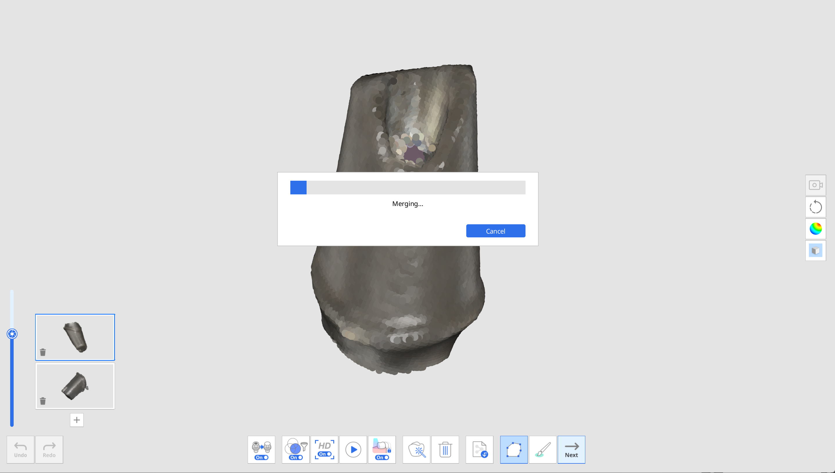
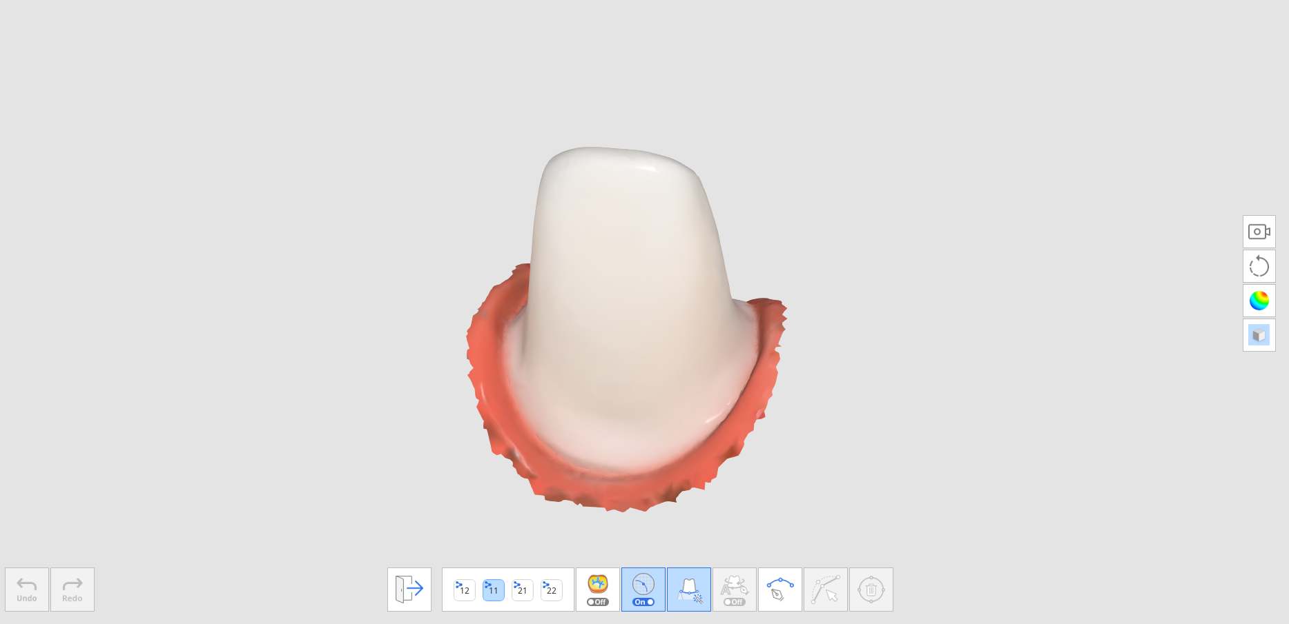
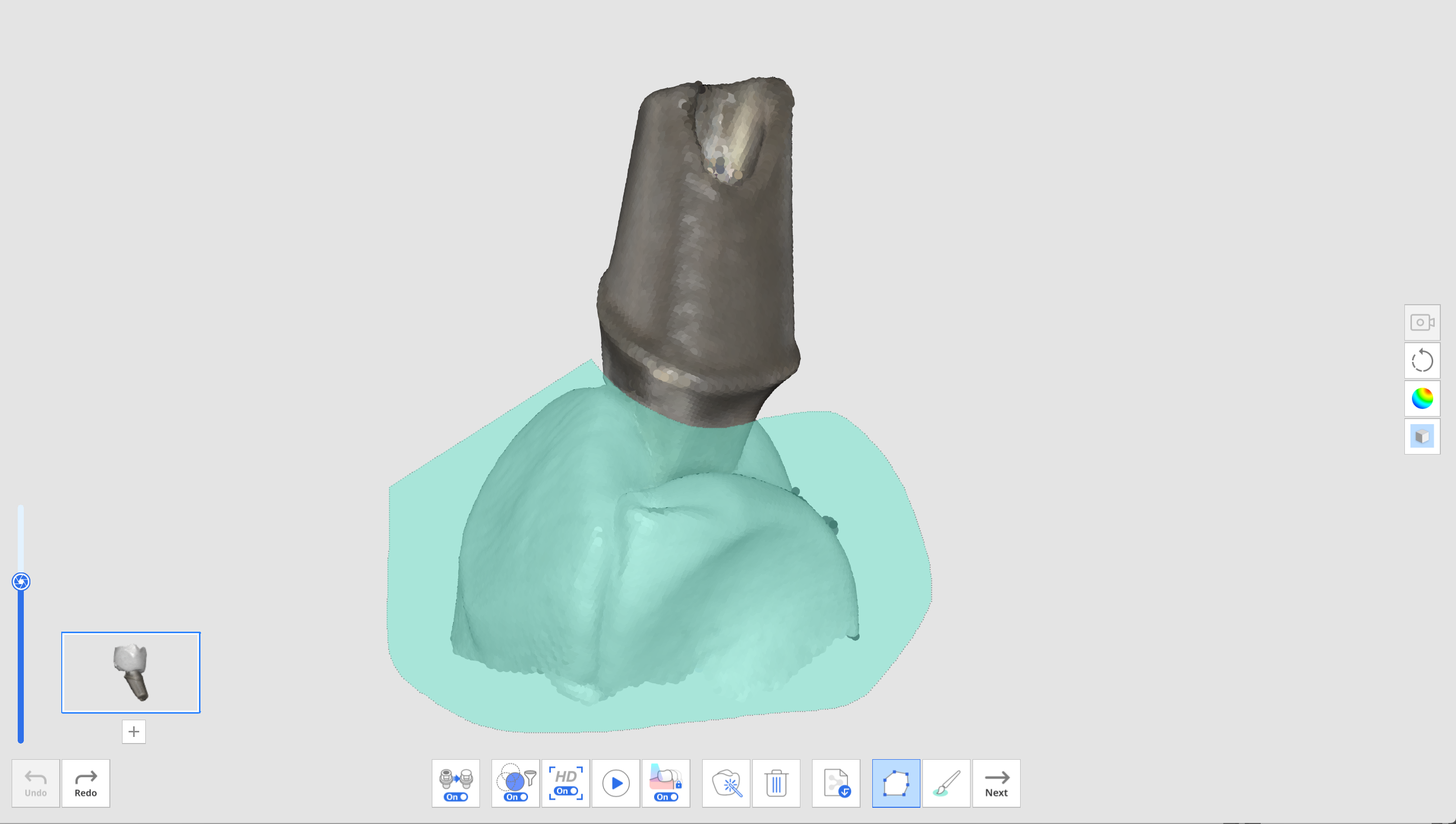
- When the merge is complete, the abutment is displayed on the screen. You can remove the auto-filled holes or edit the abutment data with Polyline and Brush Trimming tools if necessary.
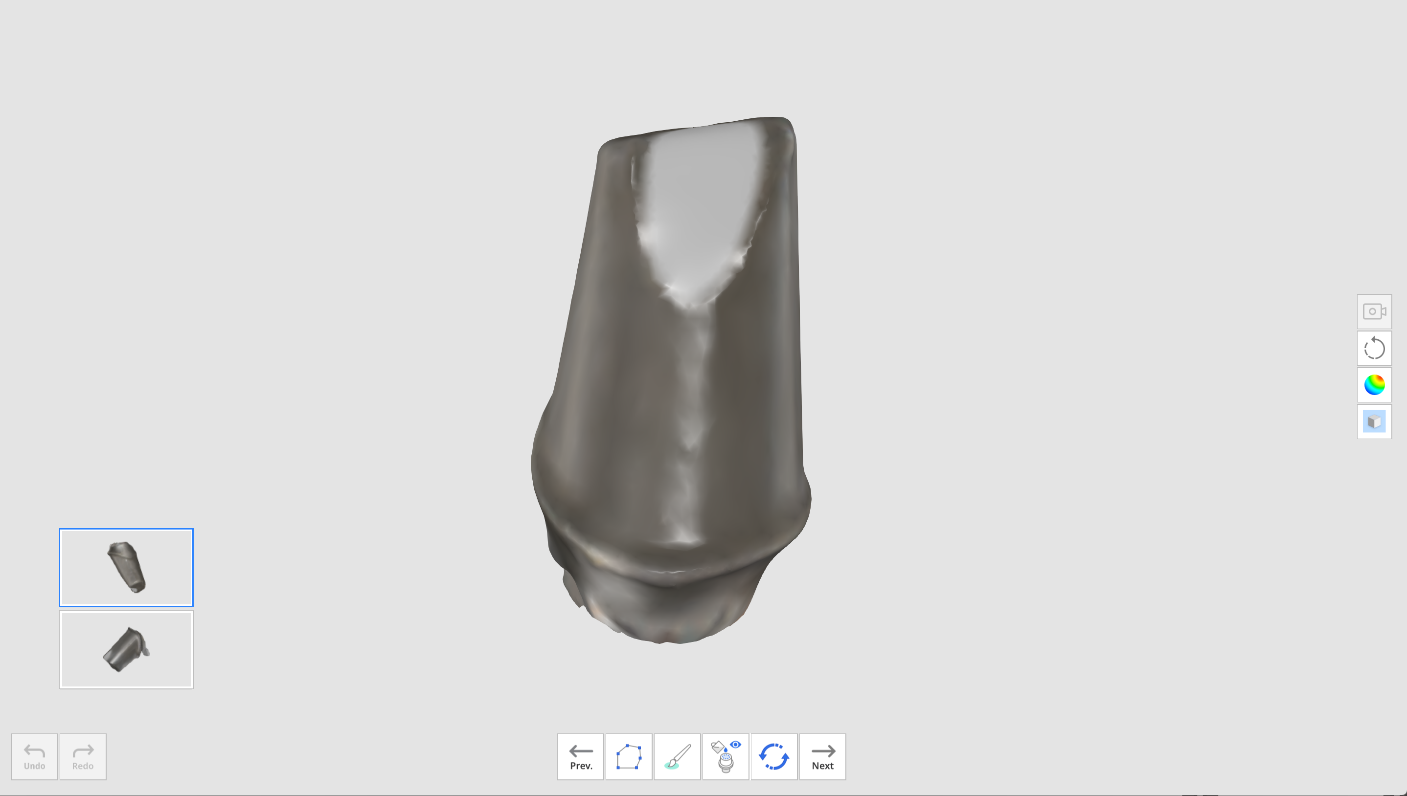
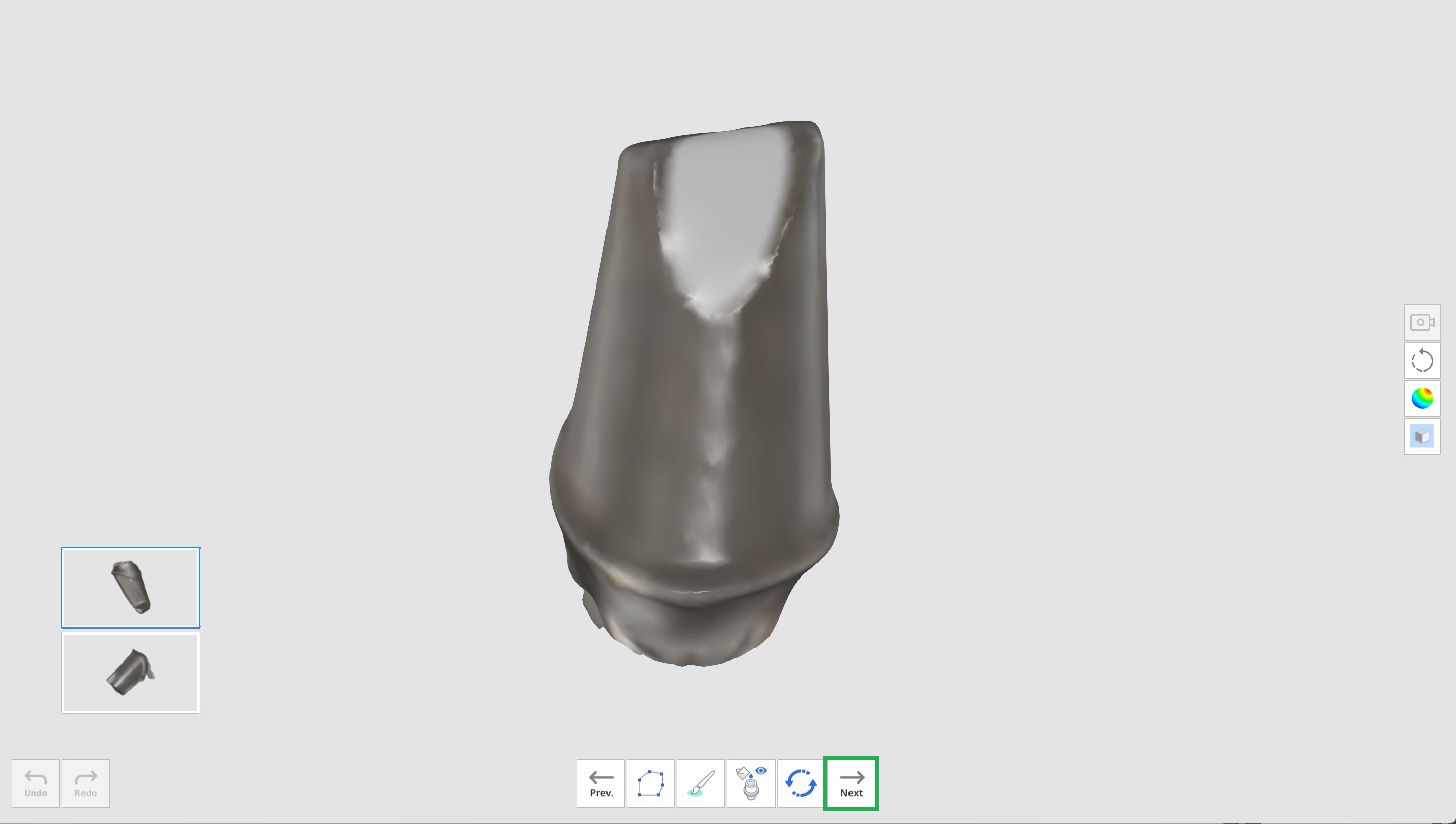
- Click the "Next" button when editing is complete.
- Enter the name of each merged abutment and click "Confirm."
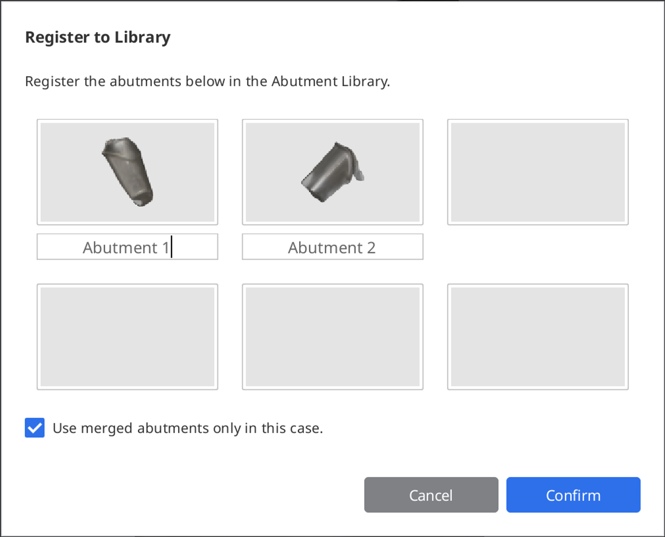 🔎NoteIf you want to keep and use the abutment libraries for other cases, uncheck the "Use merged abutments only in this case" check box.
Then, the libraries will be registered in the Collections tab instead of the Single-Use tab on the Abutment Library window so you can save and use them in other cases later if needed. - Check if your abutments are successfully added to the library when the Abutment Library dialog appears.
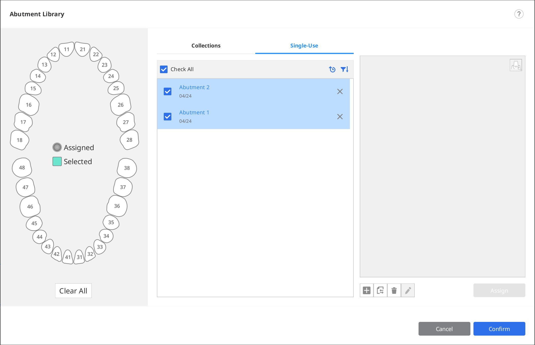
- Click "Confirm" to close the dialog.


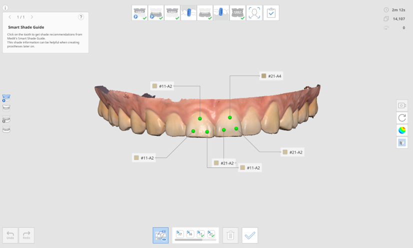
Smart Shade Guide
🔎Note
This feature is unavailable with data acquired with the i500.
The Smart Shade Guide will recommend the closest shade using data analysis.
We support the following shade guides:
- VITA Classical
- VITA 3D-Master Shade Guide
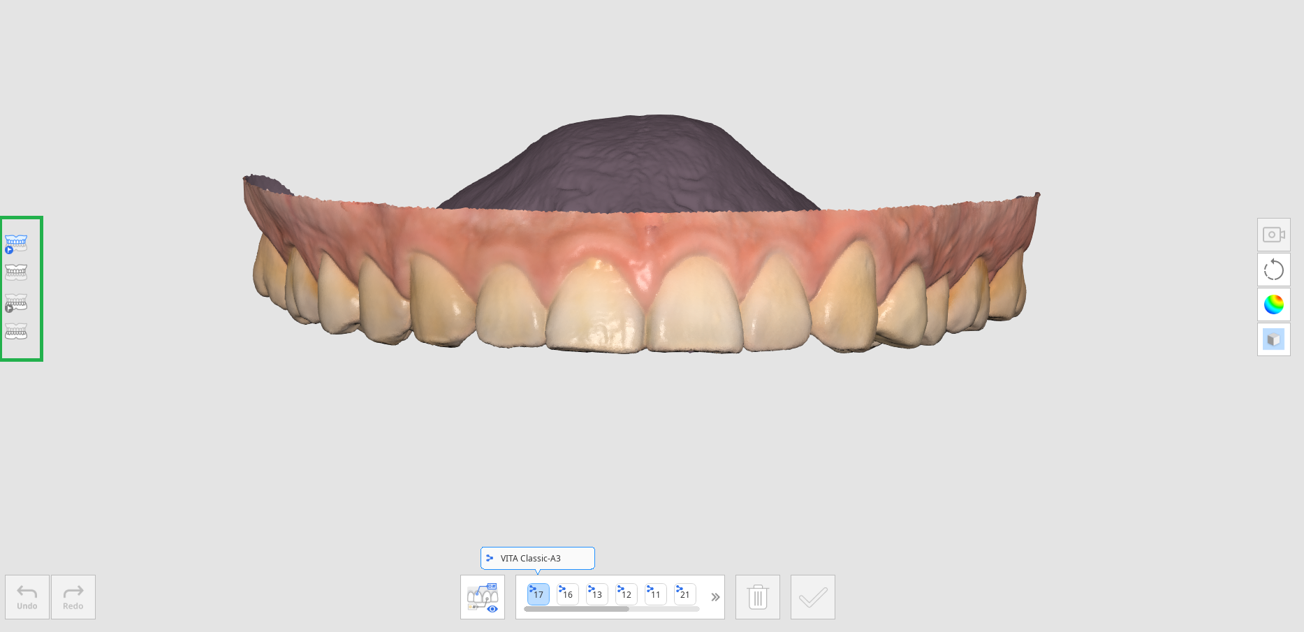
- After scan data acquisition, click the "Smart Shade Guide" tool icon on the Main Toolbar.

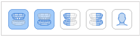
- Click on the scan step icon on the left side of the screen to select the area for which you want to receive measurements.
- Pre-Op for Maxilla
- Pre-Op for Mandible
- Maxilla
- Mandible
- Maxillary Denture
- Mandibular Denture
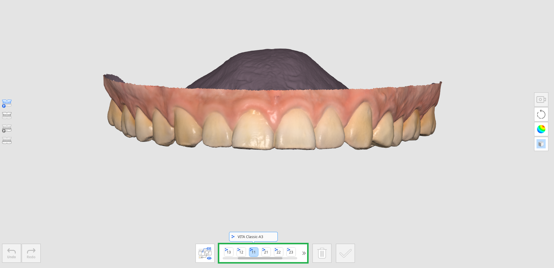
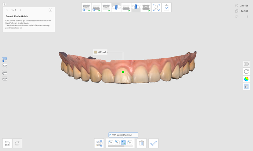
- Select the tooth number from the list of tooth numbers at the bottom. Clicking on the tooth number will display the shade information registered in Medit Link.
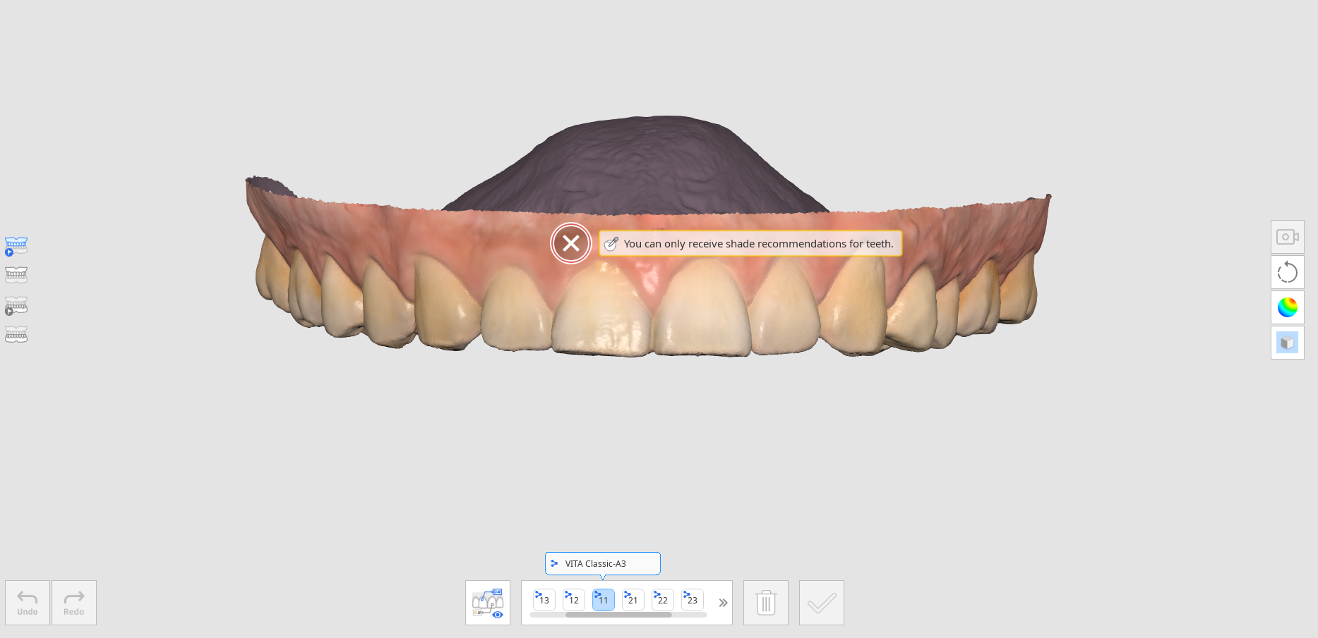
- When you hover the mouse cursor over the scan data for that tooth, the cursor changes its shape for shade recommendations. If you hover over a non-measurable area, you will be informed that the measurement is not feasible.
- Left-click on the tooth area to see shade recommendations. The star icon indicates the closest matching shade.
- If you want to designate a shade other than the recommendation, click "Manual" and select the desired shade from the list.
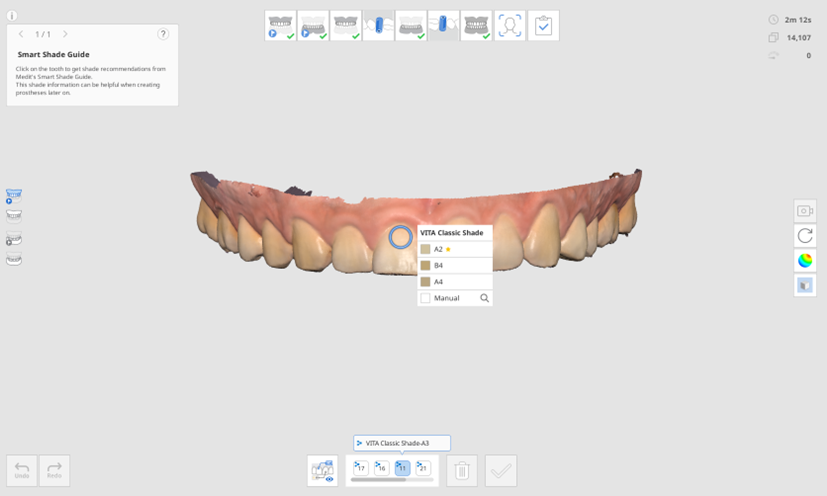
- Click the desired shade from the list.
- You can save up to five shades per tooth.
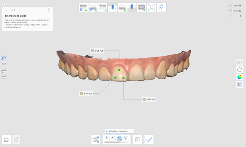
- After selecting all shades, click "Confirm Shade" at the bottom.
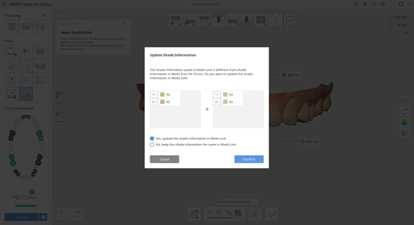
- The shades selected for each tooth are shown on the Update Shade Information dialog.
- Select the representative shade that will be saved to the Medit Link.
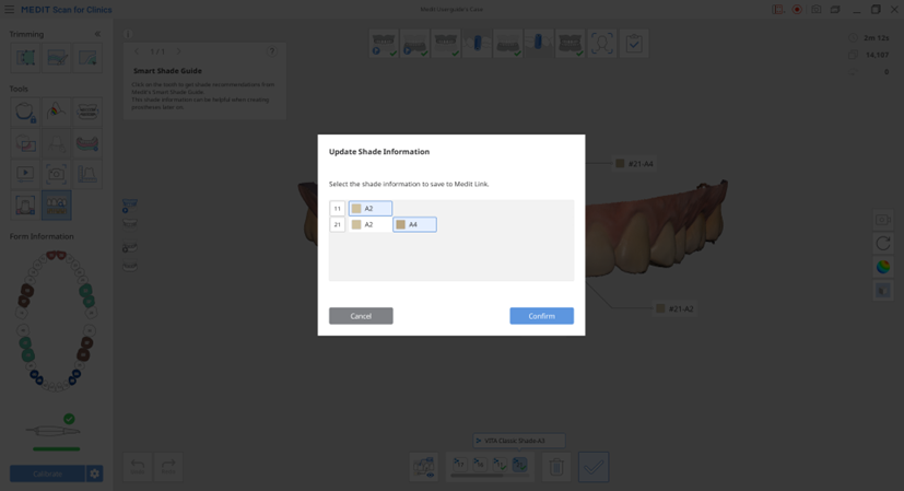
- Click "View All" to display all shade information.
- When completed, select how you'd like to update the form information in Medit Link.


Was this article helpful?
